One of the trickiest parts of writing my cycle exact 8088 emulator is going to be figuring out exactly when each part of each instruction is executed - in particular, at what point during each instruction's execution is each of its bytes removed from the prefetch queue? And (for instructions which do IO) at which points during the execution are those IO requests sent from the Execution Unit to the Bus Interface Unit?
I was originally thinking that I would have to devise a clever set of experiments to find out - make a hypothesis about the timings, devise an experiment which behaved differently depending on whether that hypothesis was true or not (existence proof: if such an experiment were not possible I wouldn't care about the result for emulation purposes), rinse and repeat until the observed behavior of the emulator stops deviating from the observed behavior of the actual machine.
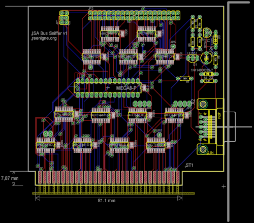
However, I have learned that there is a easier way to go about it. It turns out that the CPU outputs a couple of bits of information concerning the state of the prefetch queue on two of its pins (QS0 and QS1), allowing us to distinguish between 4 possible operations which can occur on each cycle: first byte of opcode removed, subsequent byte of opcode removed, queue emptied and no change. Being able to read that information (along with exactly what the bus is doing) would make figuring all this out much easier. I didn't want to use a logic probe to do this because (among other reasons) I wanted to be able to set up a large number of experiments and run them all automatically. So instead I have designed an ISA card which (completely transparently to the PC or XT it's plugged into) uses a microcontroller to sample the state of many lines and transmit the results to another PC over a serial connection.
Compared to a real logic probe we can only sample a few lines at once, only gather a couple of KB of samples at once and can't sample very often (I think 4.77MHz should be possible), but the experiments I care about are all deterministic so we can just repeat the experiment enough times to gather all the data I want. Here's the schematic for the bus sniffer and here's what the board layout looks like:

I've ordered a PCB from BatchPCB (the first time I've actually had a PCB professionally made) so we'll see how it works!
[…] years ago, I designed the ISA bus sniffer, a sort of special-purpose logic analyzer for capturing the signals from the CPU and ISA bus in an […]