Modifications to a programming language for ravioli

February 15th, 2016

I'd like to do some experiments with the ravioli memory I've been writing about in the past few blog posts. To give it a fair test I'd need a decent body of code (like a compiler) written in a language that I have control over. This is another reason I want to make my own compiler.

Some language modifications would be necessary to make good use of ravioli. While ravioli could be used with any non-garbage-collected language, to minimize the overhead it would be a good idea to add some language features which ensure that there is no duplication between the "low level" information used by the ravioli themselves and the "high level" information stored in the ravioli. For example, you would not want to implement reference counting on top of ravioli since the ravioli themselves have something even better (reference enumeration). Also you'd want to make sure that the vtable pointers used by the ravioli to determine where the pointers are in a given raviolo (and, if reference trees are used, whether it is normal or reverse) are also used for the high-level atoms or vtables.

I'm not sure quite what modifications to ALFE could be made to help with ravioli. I suspect most of it is just re-implementing low-level data structures, but I guess I'll find out what else can be done when I implement it.

Reference trees for ravioli

February 14th, 2016

One thing that always bothered me about ravioli memory is that deleting a node can take O(n) time because the raviolo that was moved into the new gap might have a large number of pointers pointing to it. While the behavior will probably be O(1) amortized, it's quite possible to have a pathological case when deleting a large chunk of memory, leading to O(n2) behavior. Though that could probably be mitigated by not moving any ravioli until we're done deleting (i.e. having separate deallocation and move steps).

Or we could turn the move operation from O(n) to O(1) by limiting the number of pointers which can point at any raviolo. We can do this by having two types of ravioli:

  1. The normal type, which is pointed to by exactly one pointer. Each normal raviolo has a "parent" entry which points to that pointer.
  2. The reverse type, which can only point to one other raviolo (the "target") but which has two ravioli pointing to it. Each reverse raviolo has two "parent" entries which point to those pointers.

So, if you dereference a pointer expecting to find a normal raviolo but instead find a reverse raviolo, you need to (repeatedly) follow the "target" pointer of the reverse raviolo until you find a normal one. This may have to happen O(log(n)) times, so there is an additional cost to dereferencing (although array and object dereferencing is already O(log(n)) with the previous ravioli.) In return, moving (and hence deleting) becomes O(1) as there are at most 2 pointers to update. So this type of ravioli might be better for applications where the data is changed a lot, whereas the earlier type might be better for applications where the data mostly doesn't change but is queried a lot.

With this scheme, each raviolo only needs 4 pointer-sized entries: one for the vtable, one for the parent pointer (or target pointer for a reverse raviolo) and two for normal pointers (parent pointers for a reverse raviolo). Though (possibly depending on the type of data involved) it might be worth using 8-pointer ravioli to make the trees shallower and reduce overhead. 8-pointer reference tree ravioli could also interoperate with linked-list ravioli.

For an array of simple data, 4-pointer ravioli has an overhead of 300%. However, such arrays are growable/shrinkable for no extra cost, and you can even insert and delete elements in the middle without copying the entire array. 8-pointer ravioli has an overhead of 60%.

Modifying a pointer also involves O(log(n)) operations, as it may involve rebalancing the reference tree (the tree of reverse ravioli pointing to the old and new targets of the pointer). It could actually take much longer than that if you're deleting the last reference to a large data structure, since you'd have to delete all those ravioli. That's true for all reference counting systems, though, and there's no scope for pathological behavior since any given raviolo can only be deleted once.

The set of ravioli in a program at any given point in time form a graph. It would be interesting to visualize these graphs for a complicated program and see what patterns they make and how they change with time. This would also be a useful debugging tool - especially if you can delve into the actual values in each raviolo.

2-forward, 1-back list for ravioli

February 13th, 2016

It turns out that having three "low-level" pointers per "high-level" pointer is not actually necessary in ravioli memory - two is enough.

The reason for this is that all the entries in the linked list are actually the same, so we don't need to store the pointer value in every element of the list. What we can instead do is to have two types of node:

  1. A node containing the pointer to the target and a pointer to the next node in the linked list.
  2. A node containing a pointer to the next node in the linked list and a pointer that points back in the linked list either 2 or 3 entries.

To find the target pointer if you have a node that doesn't contain it, just advance through the linked list until you do. To add a pointer to the linked list, add a forward pointer if that would cause the next backward pointer to point back 3 entries, otherwise add new backwards pointer so there are two "back 2" entries and the invariants are maintained. To remove a pointer, do the opposite to adding it.

If we want to make each raviolo a power of 2 bytes in size, we can then have 3 "high-level" pointers per raviolo (it doesn't allow us to make the ravioli smaller, since we still need a pointer for the vtable and to the first entry in that node's reference list).

However, I've since moved on to a more conceptually clean version of ravioli, which I'll talk about tomorrow.

Scrolling game edge tile list

February 12th, 2016

Suppose you're writing a scrolling game for very limited hardware. You have a frame buffer which is larger than the visible screen, but smaller than the entire level. So when the screen scrolls upwards (for example) you may need to plot a new set of tiles into the frame buffer just above the current screen position, so that the correct image will be displayed when the top of the visible screen overlaps the space where those tiles are plotted.

Now suppose that the hardware is so limited that there is not enough CPU time to plot an entire row of tiles each time you pass a tile boundary - perhaps you can get 60fps normally, but every time you pass a tile boundary you drop a frame or two while the new row of tiles is drawn into the frame buffer.

To avoid this glitch, instead of drawing all tiles at once, we can just draw one or two each frame. Suppose there are N tiles horizontally across the screen, and it takes M frames to scroll upwards by the span of 1 tile. Then we can draw N/M tiles each frame, and by the time the top of the screen gets to the bottom of a particular row of tiles, all of those tiles have been drawn.

Now we need to keep track of which tiles have been drawn and which haven't. The obvious way to do this would be to just have an array of bits, 1 for "tile has been drawn" and 0 for "tile needs to be drawn". Now, each frame when we draw a tile we can iterate through the array to find the first tile that hasn't been drawn and draw that one.

But what if there are rather a lot of tiles? Iterating through all those slots to find a "needs to be drawn" one could take a while, especially if all the undrawn slots are all the way over to the right. So we've turned a O(N) operation (N being the number of tiles drawn) into a O(N2) operation. Oh, and did I forget to mention that this is a 2D scrolling game? So we'll have a similiar list for each side of the screen, and each time we pass a tile boundary going vertically, we'll have to shift the left and right lists one tile.

How can we get rid of this quadratic behavior? Well, I think a data structure that should work well is a linked list. If we put the information about one tile slot in each node of the list, that makes it O(1) to shift the whole list one tile forwards or back for lateral scrolling, but doesn't fix the O(N2) search behavior. However, notice that we only need to store 1 bit of information about each tile slot. So what we can do is apply a run-length-encoding transformation to the list. Each node stores a pair of numbers - the length of a run of drawn tiles and the lengh of a run of undrawn tiles immediately following it.

Now all the operations we need are O(1). For the "top of screen" list, scrolling left or right by one tile just involves adding a slot to one end of the list and removing one from another. Finding the next tile to be drawn just involves looking at the first element of the list. We need two more operations: throwing away the entire list and replacing it with an "all drawn" list (for scrolling downwards) and throwing away the entire list (hopefully a single "all drawn" entry) and replacing it with a "none drawn" list (for scrolling downwards). Throwing away a list with potentially many entries sounds like it could potentially be an O(N) operation, but as it's a linked list we can move all the nodes to a "free nodes" list just by modifying the ends.

As always where performance is concerned, be sure to actually benchmark this before using it - depending on the hardware and the number of tiles in question, all that pointer chasing and cleverness may actually be slower than the naive bit array method. This is especially true if you're not in a hard-real-time situation, and the average case behavior matters more than the worst case behavior. Constant time algorithms have a definite appeal from an the aesthetics pespective, though.

The MuT music tool

February 11th, 2016

For 8088 MPH I wrote a tool to convert Amiga MOD (module) files to the format required for playback with the 4.77MHz 8088 PC speaker 4 channel playback routine. The MOD file solution never felt quite ideal to me because the playback routine has some possibilities (like SID-style ring modulation) which can't be expressed in a MOD file and there are also a lot of things you can do in a MOD that won't really work with my player, so if I make it easy to try arbitrary MODs with the player, people are likely to try MODs that don't come out very well and conclude that the player is rubbish.

What I really wanted was to write my own tracker designed specifically for the player routines I had written (and some variants that I might want to write). But writing a whole tracker is a big project - particularly the GUI (GUIs take ages and aren't the most interesting things to program).

So I started thinking: what's the simplest piece of software I could write that a musician could use to compose music for this player? What about a command line tool - a sort of compiler which accepts text files as input and generates binary music data in the appropriate format (or indeed various formats) as output? This isn't entirely unprecedented - there have been various tools for processing text files into music such as Grigasoft's "Polyphonic Music" and John Worley's "Clockwork Pianola".

This is the design I came up with - I'm calling it "MuT" ("music tool", pronounced "mute") for now - it can't seem to decide if it's a tracker, a musical instrument or a programming language.

Inside the text files we would probably want to have something similar to a more traditional tracker's pattern grid, with different channels arranged horizontally and time going vertically. Rather than using semantically-significant spaces and newlines (which cause all sorts of trouble) I think a nice way to do it would be for the musician to lay out the grid using the "&" character to separate voices (think "C & E" means a C and an E playing at the same time) and the "|" character to indicate a new time division (think "bar is a measure of time" though the "|" interval would usually be shorter than a musical bar, obviously). So an empty grid would look something like:

output =
     &     &     &     |
     &     &     &     |
     &     &     &     |
     &     &     &     ;

The spaces could then be filled in with notes:

output = sine@(
 C4 & E4 & G4 & C5  |
 C4 & E4 & A4 & C5  |
 C4 & F4 & A4 & C5  |
 D4 & F4 & A4 & D5  |
 D4 & F4 & B4 & D5  |
 D4 & G4 & B4 & D5  |
 E4 & G4 & B4 & E5  |
 E4 & G4 & C5 & E5  );

Leaving a space blank causes the note in the same voice in the previous division to continue, so this could also be written:

output = sine@(
 C4 & E4 & G4 & C5  |
    &    & A4 &     |
    & F4 &    &     |
 D4 &    &    & D5  |
    &    & B4 &     |
    & G4 &    &     |
 E4 &    &    & E5  |
    &    & C5 &     );

If you want to silence a voice, put a 0 in there instead of a blank:

output = sine@(
 C4 & E4 & G4 & C5  |
 0  & 0  & A4 & 0   |
    & F4 & 0  &     |
 D4 & 0  &    & D5  |
 0  &    & B4 & 0   |
    & G4 & 0  &     |
 E4 & 0  &    & E5  |
 0  &    & C5 & 0   );

One can also put different instruments into the grid:

output =
 sine@C4 & square@E4 & triangle@G4 & bell@C5  |
 sine@C4 & square@E4 & triangle@A4 & bell@C5  |
 sine@C4 & square@F4 & triangle@A4 & bell@C5  |
 sine@D4 & square@F4 & triangle@A4 & bell@D5  |
 sine@D4 & square@F4 & triangle@B4 & bell@D5  |
 sine@D4 & square@G4 & triangle@B4 & bell@D5  |
 sine@E4 & square@G4 & triangle@B4 & bell@E5  |
 sine@E4 & square@G4 & triangle@C5 & bell@E5  ;

Instrument names are resolved per voice, and "." is (by convention) a sort of default instrument name, so this can also be written:

output =
 { . = sine; } .@C4 &
      { . = square; } .@E4 &
           { . = triangle; } .@G4 &
                      { . = bell; } .@C5  |
               .@C4 & .@E4 & .@A4 & .@C5  |
               .@C4 & .@F4 & .@A4 & .@C5  |
               .@D4 & .@F4 & .@A4 & .@D5  |
               .@D4 & .@F4 & .@B4 & .@D5  |
               .@D4 & .@G4 & .@B4 & .@D5  |
               .@E4 & .@G4 & .@B4 & .@E5  |
               .@E4 & .@G4 & .@C5 & .@E5  ;

One can make instruments in all sorts of ways. A few simple (chiptune-esque) waveforms are built into the program, or you can load them from a file:

bell = load("BELL.WAV")@s/440;

The MuT syntax is extremely flexible and rich enough to do just about any kind of audio processing, and hopefully it's also intuitive enough that it's not too difficult to figure out how to do just that.

What follows is a more technical and in-depth explanation, so if you're not a programmer or mathematician you might want to stop reading here.

Basically most MuT objects are functions from the real numbers to the complex numbers. Both the range and domain of these functions have units (some integer power of seconds - s) which are tracked by MuT so that it can distinguish between time-domain functions like sine@C4 and pure functions like sine.

There are various operators for acting on MuT objects:

+ - pointwise addition: output = sine@C4 + square@E4; sounds the same as output = sine@C4 & square@E4; but it has some different behavior in other ways - you can't do the "empty space means continue playing the same instrument in that voice" trick if you use + instead of & in your grid, and you can't use a + b as an l-value.

- - pointwise subtraction: same as + but the function on the right has its phase inverted.

* - pointwise multiplication (aka modulation). Also useful for volume envelopes.

/ and ^ - pointwise division and power respectively. Mostly for completeness sake, though they do have some uses especially for scalars.

[] indexes into a function, just like an array in C or Pascal. So sine[1] = 0.841.... When you put a function instead of a scalar inside the brackets, you (naturally) get function composition. So a[b][x] = a[b[x]].

{} allows execution of statements during the evaluation of an expression. This is handy for redefining instruments while inside the grid (see example above), or changing the tempo, amongst other things. The tempo (i.e. the amount of time covered by one "|" is set by the special variable division. So if MuT sees { division /= 2; } inside an expression, the following grid rows will be played at twice the speed (only durations are affected, not frequencies). The scope of any changes inside {} is the remainder of the statement in which it occurs.

@ - basis scale. This is where it gets really interesting. This is an operator only applicable to functions, not scalars (so unlike +, -, *, / and ^ it isn't found on calculators). Suppose you have a function f and a scalar x. Then (f@k)[x] = f[k*x]. So if f is a waveform then f@2 is the same waveform played twice as fast (and an octave higher). The @ operator also adjusts domain units if the right-hand side has a value which is not dimensionless. So, if f has a dimensionless domain (e.g. sine) then f@110*Hz (or f@110/s) will be a normal time-indexed waveform (i.e. a sine wave with a frequency of 110Hz). As I'm sure you can see this is a very useful operator for an audio program!

It gets better, though. Suppose we have a complex unit i = sqrt(-1); and we make f@i compute the Fourier transform of f. Surprisingly, I discovered (after defining it that way) that the mathematics of doing so work out very neatly - time scaling and Fourier transformations are closely related, mathematically - they are both Linear Canonical Transformations, and there's a nice mapping from complex numbers to LCTs which gives an (efficiently computable) meaning to f@z for any complex number z. Using f@i in combination with * allows us to do convolutions and therefore any linear filters you care to describe (high-pass, low-pass, band-pass, notch, echos, resonances, you name it). Using other complex numbers on the right-hand side of @ gives us inverse Fourier transforms and fractional Fourier transforms (the musical utility of which I know not, but I'm sure inventive musicians will find some interesting uses for it).

One can also use a function on the right-hand side of @, which will result in a different basis scaling for each sample in the output - i.e. for scalar x and functions f and w, (f@w)[x] = (f@(w[x]))[x]. That's how the first non-trivial example above works.

& - next voice operator. This just puts moves to the next voice, as we've seen above. It can also be used on the left-hand side of an assignment: (a & b) = (c & d); does the same thing as a = c; b = d;. This is useful for grouping values together into a compound object.

| - time sequence operator. c = a | b yields a for division followed by b for division. Functions in MuT repeat once they are complete, so if you evaluate c in a time sequence with a sufficiently long division, it'll sound like a | b | a | b | .... Similarly you can loop a division-long section of just one function by doing c = a | ;.

As with &, | can be used on the left-hand side of an assignment: (a | b) = c; assigns the part of c between 0 and division to a and the part of c from division to division*2 to b. So by using just assignment, the special division variable and the | operator you can make whatever edits to a waveform you like.

The comparison operators ==, !=, <, <=, >, >= work the same way as their C equivalents, yielding (in general) a function whose values are boolean (true, false) elements rather than numbers. These can be used with the ?: operator to combine two functions via a predicate.

The % operator has a couple of uses (which I might change to use different characters). On its own it gives the output from the previous voice in a voice set, which is useful for ring-modulation style effects (such as those that can be done by the SID chip and by my MOD player routine). If it comes immediately after a sequence, it yields a function which is the time-to-index mapping of that sequence. So (a|b|c)% is a function that is 0 from 0 to division, 1 from division to division*2 and 2 from division*2 to division*3. You can also change the time-to-index mapping of an l-value by assigning to this function. If the time-to-index mapping function takes a non-integral value at any point then the corresponding two elements of the sequence are mixed, so you can create fades and glissandos. Time-scaling the time-to-index mapping function will speed up or slow down the playing of that sequence without affecting the frequencies.

If you combine (via multiplication or basis-scaling) two functions which don't have the same domain units you end up with a compound object. When this compound object is basis-scaled, it'll move the dimensions of the compound object closer and leave other elements unchanged. So you can create an instrument by combining a waveform (dimensionless domain) and a volume envelope (time domain), and when this is time-scaled the scaling will change the frequency of the waveform part without speeding up or slowing down the volume envelope.

I'm contemplating a built-in function that will convert a waveform into a sequence so that it can be time-scaled without changing the pitch (or vice-versa) in the manner of a phase vocoder, but I haven't quite got all the details ironed out yet.

Arbitrary functions can be defined: e.g. major(x) = x + x@5/4 + x@3/2; will turn any waveform or function into a major chord using its input as the base note. If we allow functions to be recursive, then (by the Church-Turing thesis) MuT becomes a Turing-complete programming language (for better or for worse).

It's handy to be able to have libraries of predefined functions, instruments, values (note frequencies, intervals) etc. Executing an include statement will read in a file and insert its contents into the program at that point (much like C's #include directive). Conventionally, a MuT input file will start with include "standard.mut"; to include the predefined variables which come with the program, or include "pc_speaker.mut"; which does the same but also sets up special variables for the PC speaker output mode.

There's some more design documents (which are somewhat out of date but cover a few more dark corners) and the beginnings of an implementation on my github. Being a command-line tool, it's not terribly user-friendly but it probably wouldn't be hard for someone more GUI-oriented than me to slap a user interface on top of it. One fairly simple user-interface for this might just be a special text editor, which plays whatever object is under the cursor whenever a particular key combination is pressed (and which highlights the parts of the MuT program which are being used to compute the currently-playing notes). An interesting enhancement would be a little knob that appears whenever the mouse hovers over a numeric value; dragging this knob changes that numeric value in real-time, changing the currently playing sound if that value is involved in it.
TPP and TTIP

February 10th, 2016

For years now, I've been seeing articles about the TPP and TTIP treaties showing up on the various link aggregators I read. Without exception these articles warn of all the terrible effects that will come to pass if these treaties are passed, in areas as diverse as copyright, consumer safety, democracy and the environment,

The general scheme seems to be this: instead of engaging in public debate to determine what the laws should be in order to properly balance corporate profits against the interests of individuals, negotiators representing various industries meet in secret to draw up a set of laws which are then presented to signatory countries to ratify as a fait accompli. There may be a lot of very positive changes in such a treaty, but separating these from the negative ones will be impossible, and as long as the positive changes outweigh the negative ones the treaty will get ratified and we'll all be subject to the result.

Why can't we all just agree to pass the good parts of the treaty and throw out the bad parts? The best explanation for this I've heard was from this episode of NPR's Planet Money podcast. Basically, different parties want different things so they will trade off against each other - "I'll improve the situation for your steel industry in my country if you improve the situation for my textiles industry in yours". Essentially, it's a set of barters, but what's being bartered is laws instead of actual goods and services.

We don't normally barter for things in everyday life - we use money instead, buying and selling. So why would we barter in our trade treaties? If these barters are mutually beneficial, why could they not be structured as a set of exchanges for money: "You pay me X to improve the situation for your steel industry in my country" and "I'll pay you Y to improve the situation for my textiles industry in your country". This should be much quicker and easier to negotiate since only one thing needs to be negotiated at a time - the value to country A of changing the laws of country B.

I think that a big part of the reason it doesn't happen like this is because that would be an explicit giveaway of public money for the benefit of a particular private industry, and therefore a bit of a hard-sell, politically speaking (which is too bad because such a series of giveaways would still leave us better off than TPP/TTIP). The cost could be offset by raising a tax on the industry in question but if the law change that that industry is trying to obtain is the elimination of a tariff then it's a wash - instead of paying country B directly with a tariff, that industry would be spending the same money in taxes to country A which then pays them to country B in the "law for money exchange".

Apart from eliminating tariffs, another major reason for these treaties seems to be harmonization of regulations. If you want to build a new product, it will have to pass certain tests before you're allowed to sell it. For a piece of consumer electronics, examples might be electrical safety tests and electromagnetic emissions tests. Now, because the laws requiring these standards are passed on a country-by-country basis, the regulations may differ from country to country. There is a thriving industry of test centers which will test your product to make sure it complies with applicable standards in all the countries where you want to sell it. In many cases, the tests don't even have to be repeated - the device just has to pass the test at the strictest setting and then all is good.

However, some unfortunate (though quite deliberate) provisions of the TPP and TTIP seek to "harmonize" these regulations by forcing them all to the lowest standard rather than the highest. Any country wishing to improve standards could be sued for it. There may be some regulations that are impossible to satisfy in two particular countries at once (meaning the companies would have to make different products for different markets, making them much more expensive than they would otherwise be) and I can see that such kinds of harmonization can be desirable for everyone (as long as they aren't weakened in the process). But again, these things can happen at the national level - no treaties need to be involved.

So essentially these trade treaties seem to be a way to take a set of massively regressive laws written by big corporations and package them up into something that can be sold to legislators as "you must pass this or our country will be left out of all this lucrative trade and the economic consequences will be disastrous".

A tale of two debuggers

February 9th, 2016

Every non-trivial compiler to have an intermediate representation - that is, a form of code that is neither the input source code nor the output binary or assembly code. Apart from the fact that neither of these are good representations on which to do many optimizations, it's also good for a compiler to be able to accept multiple different input languages and target multiple different output architectures.

A particularly important part of writing a compiler is figuring out a good intermediate representation. And one particularly important part of doing that is deciding on how to store debugging information. I'm not planning to write an ALFE debugger immanently but I expect that one would be useful eventually so I want to make sure that the infrastructure is sufficient to do so when I do.

I think that some desirable properties to have in a debugger are consistency, predictability and flexibility even in the face of highly optimized code - ideally it shouldn't even be necessary to have separate "debug" and "release" configurations - you'd debug on the same build of your program that ended up on the user's machine. Though one might still make a separate build with some extra checking, logging or other debugging infrastructure in order to investigate a particular bug.

There's two ways to approach writing a consistent, predictable debugger. One is to approach it from the machine code side: the places the debugger can stop are the spaces between machine instructions (let's call these red locations), and when it's stopped you can examine and modify register contents and memory locations. In other words, an old-style low-level debugger like DEBUG in MS-DOS, that understands nothing about the language that the program was written in.

The other way is to work from the source level. and is kind of a holy grail of debuggers. The places the debugger can stop are the spaces between statements or expressions with side effects (let's call these blue locations). Any source-level expression can be evaluated, any statement can be executed and any lvalue modified. What's more, the order in which things happen is predictable.

To understand what this means, consider the following ALFE program:

Int d = 0;
Int e = 0;
Int a() { ++d; return 2; }
Int b() { ++e; return 3; }
Int c = a() + b();

For the object code that results from the compilation of the last line, the compiler is entitled to generate the code that evaluates a() and b() in either order (since the order doesn't make any difference to the output of the program) or even both at once if that's possible in the target architecture's instruction set. However, when debugging we would like the order to be predictable - i.e. we would want the debugger to act as if a() is evaluated before b(). That's obviously a trivial example, but in real code optimizations can cause debugging to be unpredictable in far more severe ways.

One way this could be done is to ignore the binary program completely and interpret the source program (or, equivalently, rebuild the program with no optimizations and debug that). That would make the program run much slower under the debugger than when running normally (which may make it too slow to be practical - I've written programs where trying to debug using the non-optimized version was just too slow, which made debugging very tricky).

So, most debuggers don't try to be that predictable - they implement some hybrid approach. For example, executing things in machine code order rather than trying to simulate anything, and storing in the debug information an instruction address for each source code line (so that, unless explicitly stepping through instructions rather then the source code) you can only stop on instructions corresponding to source code lines.

I think a better approach (from the point of view of predictability) might be for the debugger to run the normal, optimized binary code until a breakpoint is hit, at which point it switches to interpretation, reconstructing all the information it needs about the program state from the stopped program's registers and memory. That might mean that on hitting a breakpoint in b() you might see d unincremented in the above example, but stepping through the same line of code would give a different result. I'm not sure if that causes more confusion than it solves.

Seeing e incremented before d should have no observable consequences (outside of the debugger) to the execution of the program - otherwise the compiler would be incorrect in swapping the calls. Checking that the compiler and debugger are correct is a specific non-goal of the debugger - we really have to work on the assumption that they are correct, otherwise we'd be second-guessing ourselves.

With an incremental compiler sufficiently well integrated with the debugger, interpretation is unnecessary - the debugger can invoke the compiler to add the breakpoint as a function call and recompile. The breakpoint then becomes an observable of the program, so that only the specific instances of the specific optimizations that need to be are disabled. Care needs to be taken to ensure that the format of in-memory data structures doesn't change in order that the program doesn't have to be restarted, but that shouldn't be too difficult.

Anyway, what does this mean for debug information? We need to somehow relate items in the object code to items in the source code and vice-versa. What does this mean in practice?

For one thing, we'll need to find a relationship between red locations and blue locations. One way to represent this would be a linked list of locations which may be either red or blue or purple (for the case where a red location perfectly coincides with a blue one). Given a location and type, you can obtain the next red location, the next blue location, the next purple location or the next location of any colour. This isn't sufficient for all optimization transformations (for example in a nested loop swapping the inner loop with the outer one so that the former becomes outer and the latter becomes inner) but it's a start.

The other thing we need is enough information to reconstruct the value of any variable given the register values and memory contents (and vice versa, for going back to the "running" state after interpreting for a while). The naive way of doing that would be to have a big matrix with red locations horizontally and variables vertically, and in each cell an algorithm for computing that variable and another for modifying the machine state when that variable is modified. Obviously that would take far too much memory for all but the most trivial programs, but it might be possible to store it in a highly compressed form, such as just storing changes to this table for each instruction.

Going back to the intermediate form, I think all this means is that I want to be able to store two things:

  • Some "pseudo-instructions" (which don't do anything to the output object code itself, but mark the position of a blue location, and have pointers to the previous and next blue locations, which may not be the same as the previous and next blue locations in the object code code). Some of these pseudo-instructions may also coincide with an actual instruction (when the blue location is between two consecutive red locations).
  • For each instruction, a list of changes to the "how to compute a high level variable" table.

ISA Bus Sniffer update

February 8th, 2016

Several years ago, I designed the ISA bus sniffer, a sort of special-purpose logic analyzer for capturing the signals from the CPU and ISA bus in an XT-class system. Well, I finally got around to finishing it, writing the three pieces of software needed to make it work (the microcontroller program, the 8088 test harness and the decoder, as well as making the changes to the XT Server to retrieve traces.

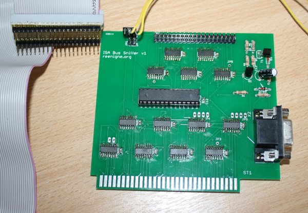
Here is what the contraption looks like:

ISA Bus Sniffer, completed

In this picture you can also see the board that goes into the 8087 FPU socket to probe the CPU pins. The yellow wires go to a switch so that I can remotely reset the microcontroller for reflashing.

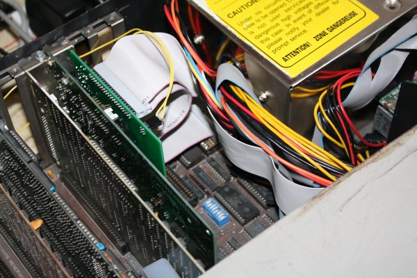
Here is how it fits into the machine:

ISA Bus Sniffer in situ

Here is what the XT Server currently looks like:

ISA Bus Sniffer in situ

And here is an example of what the output from the sniffer looks like after decoding:

20FFF .p...  00F24 FF 00 FC .......
20FFF Ip...  00F24 FF 01 FC .......                          I
20FF1 SC...  00F24 FF 01 FC .......  T1                      S F6E1         MUL CL
00F25 .C...  00F25 FF 01 FC .....D.  T2 S0
20F25 .C...  00F25 FF 01 FC .....D.  T3 S1
20F25 .C...  0020B FF 10 FC .....D.  Tw S2
20F25 .C...  0020B FF 10 FC ..r..D.  Tw S3
20F25 .C...  0020B FF 10 FC .Wr..D.  Tw S4 FF <-d [   0020B]
20F25 .C...  0020B FF 00 FC .....D.  Tw
20FFF .C...  00F25 FF 00 FC ..r....  Tw
20FF6 .C...  00F25 F6 00 FC ..r....  Tw
20FF6 .p...  00F25 F6 00 FC ..r....  T4    F6 <-f [   00F25]
20FF6 .C...  00F25 F6 00 FC .......  T1
00F26 .C...  00F26 F6 00 FC .......  T2
20F26 .C...  00F26 FF 00 FC ..r....  T3
20FE1 .p...  00F26 E1 00 FC ..r....  T4    E1 <-f [   00F26]
20FE1 .p...  00F26 E1 00 FC .......

From left to right the columns are: CPU address/data, CPU flags, bus address, bus data, DMA requests and acks, interrupt requests, bus flags, bus states for CPU and DA accesses, transfers, prefetch queue status, instruction data and decoded instruction.

You can try this out! Grab these files:
https://github.com/reenigne/reenigne/blob/master/8088/defaults_bin.asm
https://github.com/reenigne/reenigne/blob/master/8088/defaults_common.asm
https://github.com/reenigne/reenigne/blob/master/8088/trace/trace.asm
http://yasm.tortall.net/Download.html (NASM should work too with minor modifications).

Replace the code under "testRoutine:" with the code that you'd like to get a trace of (it needs to run exactly the same each time it's run, so be sure to initialize all registers and memory you use - I made that mistake and it has me scratching my head for a bit). Build trace.bin and upload it to http://www.reenigne.org/xtserver - within seconds you should get a link to a trace like the one above.

8088 MPH final version announcement

August 1st, 2015

Hornet, CRTC and DESiRE are pleased to announce a final version of our demo 8088 MPH which can be downloaded at http://www.reenigne.org/8088MPH_final.ZIP. Also a capture of the final version can be seen and heard at https://www.youtube.com/watch?v=hNRO7lno_DM. This final version has some new graphics, minor bug fixes and compatibility improvements, but it still breaks all your emulators.

Happy birthday Trixter!

More 8088 MPH how it's done

April 12th, 2015

While the 1K colour mode and 4-channel audio player are the big technical achievements I wrote for 8088 MPH, there are a few other bits and pieces in the demo I wanted to write up here. Specifically, three tricks which make possible full-screen 60Hz movement that isn't scrolling.

Starfield (particles)

This is the was the first effect I wrote for the demo, about 4 years ago. The inner loop looks like:

patchAddress:
  mov di,9999
  stosb
  shl di,1
  mov di,[di]
  es: mov [di],ah
  mov [patchAddress + 1],di

This is unrolled 948 times (once for each moving particle, with a separate patchAddress for each one). This is the number we calculated it would be possible to have if each one is updated at a rate of 60Hz (though the frame rate isn't critical here - since the particles are scanned in random order, tearing can never happen). The initial (random) value loaded into DI is the position of the particle (a value between 0 and 16383 inclusive, a byte address in video RAM). The value in AL is zero, so STOSB erases the particle. Then the lines "shl di,1 mov di,[di]" move the particle - the data table at DS:0 to DS:32767 is a sort of cross between a circular linked list and a vector field, describing the trajectory that each particle follows. So topologically speaking the particles are all moving around in a loop, but the points along this loop are arranged so that they form trajectories which look like the movement we want. The shift is necessary because the vector table is two bytes per element but the other uses of DI are one byte per element.

The line "es: mov [di],ah" plots the star on the screen. We actually have 7 different colours of stars, held in AH, BL, BH, CL, CH, DL and DH. These registers are initialized appropriately at startup, and the register that each iteration of the unrolled loop uses is set at random.

My first version of this effect included 21 different vector fields but unfortunately they don't compress well (and the best ones take ages to compute from first principles) so we ended up just using a single one and including it in the binary instead of generating it at run-time.

Moire

This can be done with practically 0 CPU time on Amiga by means of multiple bitplanes scrolling independently. We don't have that facility on CGA so it's a bit more CPU-intensive but still pretty straightforward. We use 40-column text mode to avoid snow, and do the same "right half bar" (0xde, ' ▐') trick that is used for 160x100x16 mode (based on 80-column text mode). The number of scanlines per row is set to 4 to create an 80x50 "chunky pixel" mode (though actually we only had enough time for 47 rows at 60Hz, so we just left the last few rows blank).

The large bitmap (picture of circles) is actually stored in the executable rather than computed at runtime. A second copy is created at runtime (shifted over by one half-character). Two pointers into these bitmaps are maintained in the registers SP and BP and we process four pixels per iteration of the inner loop, which looks like this:

  pop ax
  xor ax,[bp+99]
  stosb
  inc di
  mov al,ah
  stosb
  inc di

This is unrolled 940 times (20 times per row, 47 rows) with appropriate "+99" adjustments in each row, and adjustments to SP and BP are made after each row of 20:

  add sp,stride-40
  add bp,stride

To make the transition effect at the end, we overwrite blocks of these instructions by replacing the "xor ax,[bp+99]" instruction with "mov ax,0".

Unfortunately once we added the music the effect no longer runs at quite 60Hz and some tearing can be seen with close observation. This is something we hope to fix in a final version.

Kefrens bars (+raster bars)

The idea behind Kefrens bars is to get rid of the frame buffer altogether and just have a line buffer (Atari 2600 style). Then any video memory changes that you make on one scanline appear on all lower scanlines (unless overwritten by change on a lower scanline). During vertical overscan/blank/sync the line buffer is cleared. TThis has been done lots of times on other platforms, but never on CGA before. Several things make it tricky on this platform: the CGA wait states severely limit how many VRAM writes you can do in any given scanline (we ended up with 2 reads and 4 writes per scanline, plotting 7 nybble-wide pixels). The other is that you need to synchronize the routine with the CRT raster (aka "racing the beam"), meaning cycle counting and tuning the routine to take exactly 304 cycles.

Normally it's not possible for piece of 8088 code to always take exactly 304 cycles - the reason being that every 72 cycles PIT channel 1 wraps and triggers DMA channel 0 to refresh a row of DRAM, stealing the bus from the CPU for 4 cycles. As 304 is not divisible by 72, these refresh cycles appear at different places on the screen from scanline to scanline, so you need potentially 9 different scanline routines for the 9 different refresh phases. The number of scanlines per frame (262) is not divisible by 9 so you need potentially 9 different frame routines as well.

Fortunately there's another way that is both easier and requires less RAM. It's possible to reprogram PIT channel 1 so that the refreshes come every 76 cycles instead (exactly 4 times per scanline). While this may technically be out of spec for the DRAM chips, in practice we haven't found any machines on which the slower refresh doesn't work - in fact many require massively longer refresh intervals before they start to decay. Even the ones that crash with a refresh period of 84 or 80 cycles work at 76 just due to manufacturing tolerances. This is one ingredient we used to make the Kefrens bars work. Note that we had to put it back to 72 for the credits part as that routine's inner loop is a multiple of 72 cycles but not 76.

Another complication is that the CRTC in our CGA cards (the MC6845) does not cope well with a one-scanline-high frame (I believe it can be done, but that it requires reprogramming the CRTC a couple of times per scanline.) So instead our "line buffer" is actually two scanlines high. This gives a nice dithering effect on our Kefrens bars - we liked the way it looked, so we stopped trying to get the single-scanline version working.

The inner loop of the effect is 200 unrolled iterations of the 304-cycle:

  mov ax,9999
  mov ds,ax
  mov sp,[bx]
  pop di
  mov al,[es:di]
  pop cx
  and ax,cx
  pop cx
  or ax,cx
  stosw
  pop ax
  and ah,[es:di+1]
  pop cx
  or ax,cx
  stosw
  pop ax
  out dx,al
  mov ds,bp
  lodsb
  out soundPort,al

The routine uses two big tables. One (at DS:BX) is 200*838 elements in size (one for each combination of scanline and frame number - 200 scanlines, 838 frames). Each element of this table is 2 bytes, a pointer into the other, smaller table (at SS:SP). The total size of this table is 327kB, the largest single table in the entire demo. This big table is stored sideways (much like the sample table in the MOD player). Since we need to reload DS a couple of times each scanline already, we might as well reload it with a different value on each scanline. The "9999"s are patched with the right DS values at loop unrolling times. The entries in the SS:SP tables are 12 bytes each, and hold all the information needed for a combination of a Kefrens bar position and a raster bar colour. There are 154*16 entries (one for each such combination) and the whole table needs to be doubled in order to have different entries on odd and even scanlines. So 12*154*16*2 = 59136 bytes, fits quite happily in a single segment.

The small table can easily be generated at runtime, but the big table proved troublesome. With some heavy optimization, I got the precomputing of Puppeh's nice Kefrens bars motions and raster bars patterns down to 28 seconds or so but my target was less than 15 seconds. After a few false starts I figured out that the Kefrens bars part of the table was quicker to compute but compressed less well while the raster bars part of the table took longer to compute but compressed much better. So I ended up just splitting the tables, compressing the rasters and precalculating the Kefrens.

If you try the demo out on real hardware and the Kefrens bars effect seems unstable, try disabling any network card drivers and networking software you may have installed. IRQs from a NIC or similar hardware can mess up the delicate timings. This is one of the more timing-sensitive effects in the whole demo, though - without a 4.77MHz and genuine MC6845-based IBM CGA card the image is unlikely to stabilize.

One other thing you might notice about this routine is that it outputs to the speaker on each scanline! This was something I didn't get working in time for Revision, but my plan for this effect was that we would have PWM music playing in the background. So there's more that can be done with this effect that what we did in 8088 MPH (if not the sound, then those cycles could be used for something else).

Source code

The source file for all the bits of the demo I wrote are now up on my github:

Effects:

Tools: